
Thick-Plate Multi-Layer Multi-Pass Welding in Detail
Date: 2026-08-09
01 | Interpass Management Is the Real Challenge of Multi-Layer Multi-Pass Welding
Many people assume that thick plate welding simply means “laying down a few more passes,” believing that sufficient robot accuracy and power source output are all it takes. In reality, the difficulty of multi-layer welding of thick plates lies not in how well each individual pass is made, but in whether the next pass can still be made well after each previous pass.
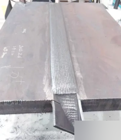
For thick plates — steel plates over 12 mm — a single-layer weld bead can never do the job. The solution? Fill layer by layer and stack pass upon pass. That is multi-layer multi-pass welding.
It sounds simple — a root pass first, fill passes next, and a cap pass last. The principle is correct, but in practice, the variables between passes are overwhelming.
The first variable: interpass temperature drift.
After the first pass, the base metal is still cold; by the fifth pass, the whole workpiece has become thoroughly heated. The temperature field is constantly changing, and heat input keeps accumulating. When the interpass temperature falls below 150 °C, the risk of hydrogen retention increases by 4–7 times and cold cracking susceptibility rises markedly; above 290 °C, the grains of low-alloy steel coarsen and impact toughness drops by 15%–22%. That is how narrow this window is.
The second variable: distortion caused by accumulated heat input.
Every pass heats the workpiece, and since the heat cannot dissipate, the accumulation effect becomes increasingly pronounced. Thin plates tend to buckle, while thick plates develop angular distortion with superimposed residual stress. According to industry measurements, when welding Q345 steel, the second pass must be deposited within 3 minutes of completing the first, otherwise the preheat effect decays by 40%.
The third variable: the bead profile of the previous pass affects the trajectory of the next.
The root pass is done, but the weld surface is not an ideal plane. Reinforcement, undercut, craters, and uneven bead formation — all of these affect the wire aiming and fusion quality of the fill layers. Your programmed path is based on the ideal groove, but the actual groove is no longer “ideal.”
The fourth variable: groove dimensions vary along the weld length.
A groove machining tolerance of ±0.5 mm is the industry norm, and assembly gap fluctuations exceeding 0.3 mm require arc tracking compensation. Over a 2-meter-long weld, the groove dimensions cannot be perfectly consistent from start to finish.
So you see, multi-layer multi-pass welding is not a “single-pass stacking” problem but a system coupling problem. The quality of each pass depends on the accumulated state of all preceding passes.
“Getting the first pass right only earns you a ticket to the game; getting the next dozen passes right is the real skill.”
02 | Robot Accuracy Is Not as Simple as “Repeat Positioning Accuracy ±0.05 mm”
Many manufacturers market their welding robots by leading with a single parameter: repeat positioning accuracy of ±0.05 mm. Does the number look good? Yes. But it has little bearing on your actual welding accuracy.
Repeat positioning accuracy describes the robot’s ability to return to the same spatial position repeatedly. That is, move the robot to point A, move it back, and move it back again — how much does the deviation vary each time? This is measured under ideal laboratory conditions.
But welding is not point-to-point motion. Welding is continuous trajectory motion, and it takes place in a constantly changing environment.
Real welding accuracy depends on three things:
🔍 First, seam finding capability (before welding)
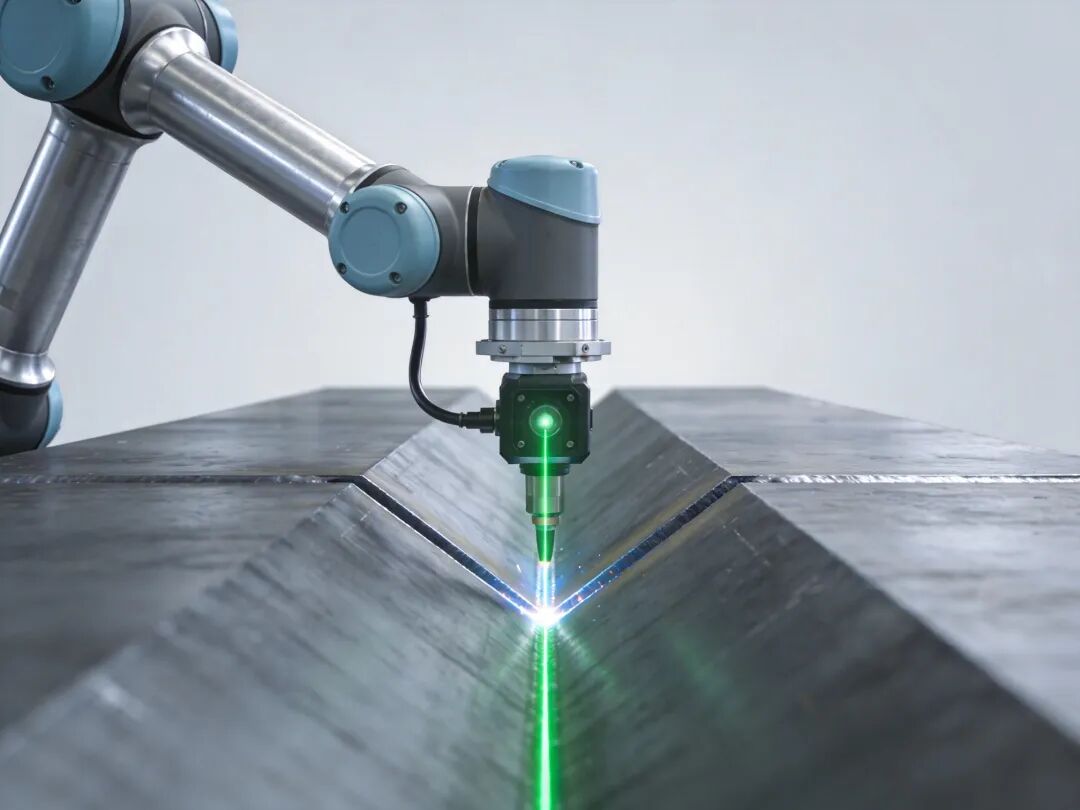
Before welding starts, the robot must first locate the seam. Through contact or arc sensing, it precisely finds the arc start point, with errors controlled within 0.2 mm.
🔍 Second, arc tracking / laser tracking capability (during welding)
During welding, the groove position changes in real time. The robot must “watch” while it welds, sensing groove position deviations in real time and dynamically correcting the trajectory. The arc tracking technology of a major international industrial robot brand achieves tracking accuracy of ±0.2 mm and can overcome groove machining errors of ±0.5 mm. Laser tracking sensors offer even higher accuracy, reaching the ±0.1 mm level.
🔍 Third, adaptive programming capability for multi-layer multi-pass welding
After the root layers are completed, the robot measures the actual weld profile through its sensing system and automatically generates paths for the fill and cap layers based on the measured data. That is what true adaptability means.
When selecting a welding robot, look at the “welding accuracy trio”: seam finding accuracy, tracking accuracy, and adaptive capability.
“A repeat positioning accuracy of ±0.05 mm welds laboratory coupons; a tracking accuracy of ±0.2 mm welds the real workpieces on the shop floor.”
03 | The Welding Power Source Is Not Just “Able to Strike an Arc” — Heat Input Control Is the Core
Some factories, to save costs, use ordinary DC power sources for multi-layer welding of thick plates. The result? 20% of welds fail inspection. Where does the problem lie? Not with the welder, not with the robot — the power source responds too slowly. When the current lags by 0.3 seconds, the root is not fully penetrated.
Multi-layer multi-pass welding places far higher demands on the welding power source than most people imagine. It is not enough to “strike an arc and feed wire”; there are four hard indicators:
⚡ First, pulse function
Pulsed mode achieves “one pulse, one droplet” metal transfer — each pulse cycle transfers exactly one droplet, with minimal spatter and precisely controllable heat input. Typical parameters: peak current 350 A, base current 80 A, pulse frequency 150 Hz.
⚡ Second, heat input deviation control
Classification societies (such as DNV and ABS) require heat input deviation of ≤ ±3% for multi-layer welding of thick plates. Heat input in multi-layer welding is cumulative — if each pass deviates by 3%, by the tenth pass the accumulated deviation already causes excessive angular distortion. Pulsed welding technology can narrow the heat input fluctuation range to within ±5%, and high-end power sources achieve ±3%.
⚡ Third, dynamic response speed
At the moment of arc ignition, the current must surge from zero to the set value within an extremely short time. The required current rise slope is ≥150 A/ms — while ordinary inverter power sources deliver only about 30 A/ms. Based on a heterogeneous DSP + FPGA control platform, current response at the 50 μs level can be achieved. Replacing conventional IGBTs with SiC MOSFET devices raises the inverter frequency from 20 kHz to 70 kHz or even 100 kHz, shortening current rise time by more than 42%.
⚡ Fourth, multi-layer welding process library
The root, fill, and cap stages require completely different process parameters. A good welding power source has a built-in multi-layer welding process library, enabling automatic parameter switching and coordinated control of interpass temperature with the robot.
In plain terms, the welding power source is the “engine” of multi-layer multi-pass welding. If the engine is weak, it does not matter how fast the car can run.
“Thick plate welding leaves far less room for error than thin plate welding. A leak in thin plate can be repaired; an incomplete fusion in thick plate must be cut out and redone.”
04 | Welding Process Services Are the Real Moat of Thick Plate Welding
Robots can be purchased from traditional industrial robot manufacturers, welding power sources can be chosen from a welding power source brand, and fixtures can be customized by any supplier. But the “how to weld” — that cannot be bought.
How should the groove be designed? V-groove, X-groove, or U-groove? What bevel angle? How thick should the root face be?
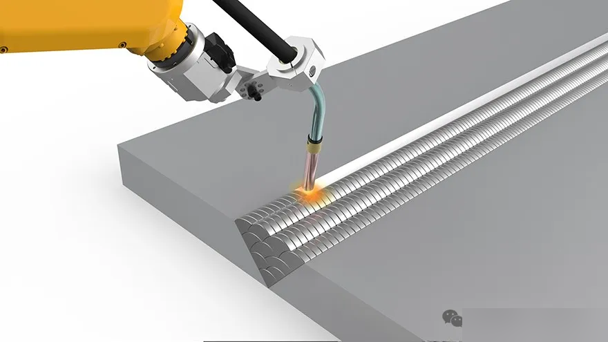
How should the passes be arranged? How many passes per layer? What weave width? How much overlap between adjacent passes?
How should interpass temperature be controlled? How should the welding sequence be optimized? How should heat input be distributed?
None of these questions has a standard answer.
Every workpiece, every material, every working condition is different. What does it rely on? Years of accumulated process experience, lessons distilled from hundreds or thousands of projects, and parameters worked out over countless tons of welded steel.
This experience is the core asset of a welding process company — and the real reason customers are willing to pay.
From power sources to robot integration, from single machines to workstations, from workstations to entire production lines — it is not just about selling equipment, but about providing “process + equipment + solution” integrated welding process services.
Thick-plate multi-layer multi-pass welding may look like a matter of equipment, of robots, of power sources. But in the end, what it truly comes down to is process accumulation.
“Equipment is the tool; process is the soul. When thick plate welding goes down to the wire, what counts is process accumulation.”