
Six Common Mistakes in Robotic Welding Commissioning
Robotic welding is evolving from “a high-end technology you admire” to “affordable productivity you can actually use.” However, many commissioning engineers new to robotic welding tend to focus on complex teach programming, posture optimization, and parameter matching, while overlooking details “too trivial to mention.” It is precisely these low-level mistakes that make an otherwise stable, efficient automated line suffer from porosity, undercut, weld misalignment, and even wire-feeding jams. This article summarizes the six most common low-level mistakes encountered during commissioning, analyzes the scientific principles and practical consequences behind each, and offers the correct handling methods — hoping to help beginners avoid detours and encourage veterans to re-examine their own habits.
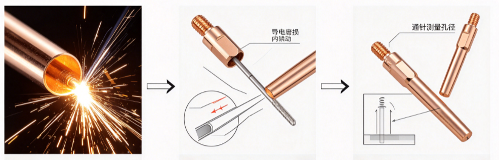
Mistake 1: Failing to Replace a Worn Contact Tip in Time
Symptoms: The arc becomes unstable, “popping” sounds appear during welding, spatter increases noticeably, the weld bead surface turns rough, and intermittent insufficient penetration occurs. Beginners usually suspect welder parameters or gas flow first, but rarely check the contact tip immediately.
Principle analysis: The contact tip is the final contact element between the wire and the welding power source. There is a clearance of about 0.2–0.3 mm between its bore and the wire. When the contact tip wears, the bore enlarges or becomes irregular, causing the wire to wobble inside the hole and the electrical contact point to shift continuously. This triggers a chain reaction:
- Fluctuating contact resistance → unstable welding current → penetration that varies between deep and shallow
- Random variation of the wire stick-out (electrical stick-out) → actual current density deviates from the set value
- Poor contact can cause arc back-burn, burning the front of the contact tip or even the nozzle
Correct practice:
- Inspect the contact tip bore after every 200–300 m of wire consumed (about 2–3 spools of 15–20 kg).
- Measure the bore with a dedicated pin gauge or plug gauge; replace the tip when the bore is more than 0.2 mm larger than the wire diameter.
- For aluminum welding, where the wire is softer and conductivity requirements are higher, increase the replacement frequency to about once every 100 m.
- Never grind or hammer a contact tip and continue using it to “save cost.”
Mistake 2: Workpiece Positioning Deviation Without Coordinate System Calibration
Symptoms: A taught program welds the first workpiece perfectly during batch production, but after changing to a new batch of workpieces, the welds shift as a whole or even cause torch collisions. Beginners often suspect insufficient robot repeatability or blindly modify program points.
Principle analysis: The “precision” of robotic welding is built on strict correspondence between the workpiece position and the robot’s base coordinate system and tool coordinate system. Workpiece positioning deviations fall into two categories:
- Absolute deviation: wear of fixture locating pins or spatter on locating surfaces causes overall translation or rotation.
- Batch deviation: stamped parts produced by the same die inherently vary in dimensions.
If these deviations are not compensated, the robot will “stubbornly” follow the taught trajectory, and the arc will deviate from the groove center. In mild cases the weld is off-center; in severe cases the contact tip short-circuits against the workpiece.
Correct practice:
- Always use the search function (also called start-point detection or seam finding). Products from most industrial robot manufacturers (such as a major international industrial robot brand) provide contact or non-contact search instructions.
- After each part change, the robot automatically detects reference points on the workpiece (holes, edges, bosses) and shifts the entire trajectory by the calculated offset.
- If batch consistency is poor, use laser tracking or arc tracking for real-time correction.
- Absolute taboo: welding repeatedly with only “hard positioning” by fixtures and no search compensation at all.
Mistake 3: Blindly Increasing Current to Chase Penetration
Symptoms: When encountering lack of fusion or insufficient penetration, operators habitually raise the welding current by 20–30 A, sometimes far beyond the recommended range, believing “more current is always better.”
Principle analysis: Penetration depends not only on current but is coupled with welding speed, stick-out, shielding gas, and groove geometry. Blindly increasing current brings a series of negative consequences:
- Sharply increased heat input: thin plates burn through directly; for medium and thick plates, it causes coarse grains, softening of the heat-affected zone, and degraded mechanical properties.
- Overly fluid weld pool: sagging and weld buildup under gravity; overhead positions cannot form a weld at all.
- Greatly increased spatter: in short-circuit or globular transfer modes, excessive current makes droplets detach explosively, and spatter blocks the nozzle and contaminates the workpiece.
- Abnormal wire burn-back: exceeding the wire’s allowable current density (e.g., a 1.2 mm solid wire is usually rated no higher than 300 A), the wire melts internally before exiting the nozzle.
Correct practice:
- Prioritize adjusting welding speed and weave parameters to improve penetration.
- When more penetration is needed, combine low current + slow speed + appropriate weaving rather than raising the current alone.
- Refer to the current limits in the Welding Procedure Specification (WPS): for 1.2 mm carbon steel solid wire, 220–280 A is recommended; for 1.0 mm, 180–240 A.
- Always validate through procedure qualification rather than adjusting current by feel.
Mistake 4: Ignoring the Influence of Ambient Temperature and Humidity on Weld Quality
Symptoms: In winter or the plum rain season, welds suddenly develop large amounts of porosity and cracks, and the bead surface turns dull or gray. Beginners check gas purity, the wire feed mechanism, and the contact tip and find no problem — but remain puzzled.
Principle analysis: The influence of ambient temperature and humidity on weld quality is seriously underestimated:
- Humidity: water vapor in the air decomposes into hydrogen and oxygen under the high arc temperature. Hydrogen is the main culprit behind cold cracks (delayed cracks) and porosity in welds. When relative humidity exceeds 80%, even low-hydrogen wires can hardly avoid excessive diffusible hydrogen.
- Temperature: in low-temperature environments, the base metal dissipates heat faster, and the weld pool cools too quickly, easily forming hardened structures such as martensite and inducing cold cracks. In addition, at low temperatures the flowability of CO₂ shielded welding deteriorates and shielding effectiveness declines.
Correct practice:
- Equip the workshop with a hygrometer and thermometer; the welding environment should be controlled at a temperature above 5°C and relative humidity ≤ 70%.
- When humidity is too high, dry the welding consumables (especially flux-cored wire) and raise the preheat temperature (e.g., preheat materials of Q345 and above to 50–100°C).
- In low-temperature environments, use flame or induction preheating before welding to slow the cooling rate.
- Aluminum welding is more sensitive to humidity: humidity should be ≤ 60%, and the wire should be used within 8 hours after being taken out of its sealed packaging.
Mistake 5: Copying Standard Weave Parameters Without Considering Plate Thickness
Symptoms: Commissioning engineers copy a set of weave parameters (amplitude, frequency, dwell time) from another project or a standard program library and apply them directly without considering the current plate thickness and groove dimensions. The result: thin plates burn through, and thick plates suffer lack of fusion at the side walls.
Principle analysis: The purpose of weave welding is to cover both sides of the groove with deposited metal through lateral torch oscillation. However, weave parameters are closely related to plate thickness, groove angle, and root gap:
- Amplitude: should be slightly smaller than the groove opening width. If too large, the dwell time on each side is insufficient, causing lack of fusion at the edges; if too small, the groove cannot be covered.
- Side-wall dwell time: in multi-layer multi-pass welding of thick plates, the torch must dwell 0.2–0.5 s on each side to let the pool fully wet the side walls. Weaving on thin plates, by contrast, easily causes overheating.
- Frequency: for thick plates, a lower frequency (1.5–2.5 Hz) is preferred to keep the pool stable; for thin plates and high-speed welding, a higher frequency (3–5 Hz) can be used.
A typical failure case: weave parameters for 8 mm plate were used to weld a V-groove in 20 mm thick plate; the weave amplitude of only 5 mm could not reach the groove side walls at all, producing a “false weld” — inspection revealed extensive lack of fusion.
Correct practice:
- Calculate weave parameters individually based on plate thickness and groove design. Basic principle: amplitude = groove root width + 1–2 mm allowance per side.
- Thin plates (≤ 6 mm) generally need no weaving; straight-line welding or slight weaving (amplitude ≤ 3 mm) is sufficient.
- After every workpiece model change, re-validate the weave trajectory and perform macroscopic metallographic or etch inspection on the first part.
Mistake 6: Failing to Clean the Torch Wire Conduit After Welding
Symptoms: After a period of use, wire feeding becomes erratic — “twitchy” feeding — and in severe cases the wire jams inside the conduit, causing downtime. Beginners often replace only the contact tip and nozzle, overlooking the conduit.
Principle analysis: Metal spatter, dust, and debris from the copper plating on the wire surface gradually accumulate on the inner wall of the conduit. In particular, trace oil and rust on steel wire form black powder under the friction of wire feeding, clogging the conduit.
Physical process of conduit blockage:
- Increased resistance → wire drive roll slippage → fluctuating actual feed speed → welding current fluctuates violently with changes in stick-out.
- In severe cases the wire bends into a “bird’s nest” inside the conduit, jamming between the drive rolls and the conduit inlet.
Correct practice:
- Every 8 hours of welding (or after each spool is used up), remove the conduit and blow it out in reverse with compressed air from the outlet end.
- Replace the conduit every 100 hours (about 2 weeks) — the cost is minimal but the effect is significant.
- Use spiral conduits with Teflon liners, which have a low friction coefficient and resist buildup.
- For aluminum wire, whose surface is soft and prone to producing aluminum chips, use a dedicated nylon conduit and shorten the cleaning interval to 4 hours.
Conclusion
Every robotic welding commissioning engineer should build a “checklist” incorporating the six items above into daily inspections and the confirmation process before each production batch. When you learn to ask yourself “Has the contact tip been replaced?”, “What is the humidity today?”, and “Were the weave parameters calculated for this plate?” whenever a problem arises, you have already surpassed 80% of your peers. Welding is an engineering science where “a miss is as good as a mile,” and a practical art where details determine success. May every arc start be stable, and every weld pass inspection.