
Multi-Layer Multi-Pass Welding Process Guide
Date: 2026-03-22
In heavy industry sectors such as steel structures, shipbuilding, pressure vessels, and aerospace, thick plate welding (thickness ≥ 6 mm) is widely applied. As construction machinery evolves toward larger scale and higher load capacity, ultra-thick plate welding of 50 mm, 80 mm, and even 120 mm has become a rigid industry requirement. However, thick plate welding is by no means a simple “stacking” of deposited metal. If the process is not properly controlled, serious defects such as lack of fusion, cold cracking, and excessive distortion can easily occur, directly compromising structural safety. This article combines the latest process research data with first-hand field experience to examine the core process recommendations, practical solutions, and key precautions for multi-layer multi-pass welding of thick plates, and also introduces the frontier trends in intelligent welding, providing industry practitioners with a comprehensive, actionable technical guide.
1. What Is Multi-Layer Multi-Pass Welding?
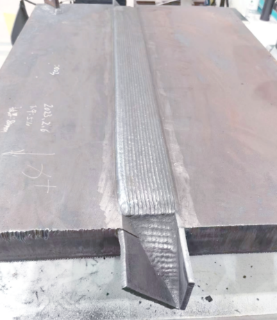
Multi-layer multi-pass welding is the core process method for completing thick plate welds by depositing metal layer by layer and pass by pass. It is mainly divided into three key layers, each with a distinct role, and all are indispensable:
- Root layer: Responsible for full root penetration, ensuring a regular weld backside profile; it is the foundation for subsequent welding.
- Fill layer: Carries out the main volume filling of the weld, gradually filling the groove while balancing penetration and stress distribution.
- Cap layer: Ensures a smooth, aesthetically pleasing weld surface, avoids stress concentration, and improves joint appearance and mechanical stability.
Core advantage: Each subsequent pass exerts a “tempering” effect on the previous pass, effectively refining the weld grains, improving the mechanical properties of the deposited metal, and reducing the incidence of defects such as cracks and slag inclusions.
2. Key Process Recommendations and Parameter Control
Multi-layer multi-pass welding of thick plates requires meticulous planning of every step, with precise control akin to “embroidery.” The following core process recommendations are based on the latest practice and research and can be applied directly:
2.1 Groove Design: The Foundation of Foundations
The groove configuration directly determines the amount of deposited metal, welding efficiency, and joint quality; rational design is the prerequisite for reducing defects:
- Narrow-gap grooves are the mainstream trend: For extra-thick plates above 45 mm, ultra-narrow-gap grooves (root gap 3–4 mm, bevel angle 1°–2° per side) can significantly reduce the amount of deposited metal, improve welding efficiency, and lower welding stress.
- Transition treatment for plates of different thicknesses: When the thicknesses of the two plates being joined differ, the thicker plate must be machined into a sloped transition; the maximum allowable slope is typically 1:2.5 (≤ 1:4 under dynamic loading), effectively avoiding stress concentration at the joint and preventing crack formation.
2.2 Root Pass: Building a Solid Foundation Step by Step
The root pass is the critical step in thick plate welding. The key is to ensure full root penetration and avoid lack-of-penetration defects: a smaller-diameter filler material (e.g., φ3.2 mm electrode) or a small spot size should be used, combined with a higher energy density. For example, in laser root welding of TC4 titanium alloy thick plates, autogenous welding at around 5 kW without filler wire is commonly used, producing a uniform, defect-free root weld.
2.3 Fill Layer: Precise Pass Layout and Strict Heat Input Control
The fill layer must balance filling efficiency and joint performance. Passes are usually divided using the “equal area method” or “equal height method,” with the core parameters controlled as follows:
- Pass dimensions: The thickness of each single layer must be strictly controlled at 3–5 mm, and the width of each pass should not be excessive, to avoid grain coarsening caused by excessive heat input.
- Current/voltage matching: As the number of layers increases, the welding current can be appropriately increased (e.g., from 110 A for the root pass to above 160 A for filling), but the heat input must remain stable and sudden parameter changes must be avoided.
- Weaving optimization: For laser welding, circular weaving (amplitude 2–2.5 mm) can be used to enhance fusion at the groove side walls; for arc welding, crescent or zigzag manipulation is common, with a brief dwell at both sides of the groove to ensure complete side-wall fusion without lack-of-fusion defects.
2.4 Interpass Temperature: The Overlooked “Invisible Killer”
Interpass temperature control is of paramount importance in thick plate welding and directly affects weld microstructure and mechanical properties:
- Control range: The interpass temperature is generally required to be equal to or slightly higher than the preheat temperature, but must never be too high (e.g., low-alloy high-strength steel typically requires ≤ 250 °C). Excessive temperature causes grain coarsening, a sharp drop in toughness, and an increased risk of cracking.
- Reference measured data: In welding of 45 mm titanium alloy thick plates, the interpass temperature must be strictly controlled at 200 ± 20 °C, which effectively ensures the good mechanical properties of the acicular martensite structure and avoids microstructural defects.
2.5 Cap Layer: Controlled Final Weld Profile
The cap weld must balance appearance quality and stress distribution. The welding current can be appropriately reduced by 5%–8% while the welding speed is increased; the electrode manipulation adopts an inclined circular or reverse-zigzag pattern to ensure a smooth transition between the weld and the base metal, free of defects such as undercut or excessive reinforcement.
3. Common Problems and Practical Solutions
In actual production, various troublesome defects are prone to occur in multi-layer multi-pass welding of thick plates. Based on first-hand experience, the common problems, core causes, and targeted solutions are summarized below:
| Common Problem | Core Cause | Solution |
|---|---|---|
| Side-wall lack of fusion | Groove angle too small, torch misalignment, or insufficient heat input | Optimize groove design and use laser weaving or arc weaving to ensure the arc precisely heats the groove side walls and achieves full fusion. |
| Interlayer slag inclusions | Slag from the previous pass not thoroughly cleaned, remaining between the weld bead and the groove | After each layer, thoroughly remove slag with a chipping hammer or grinder, paying special attention to the fusion line at the groove edges to avoid residue. |
| Cold cracking | Excessive interval between layers, temperature dropping below the preheat temperature, hydrogen unable to diffuse | If welding is interrupted, reheat (possibly to a temperature slightly above the original preheat); when welding continuously, speed up the pace to avoid a sharp temperature drop. |
| Welding distortion | Excessive heat input, unreasonable welding sequence, uneven stress distribution | Use two-person symmetrical welding or backstep welding; for T-joints in thick plates (≥ 40 mm), Z-direction steel can be selected to effectively prevent lamellar tearing. |
| Porosity (aluminum alloy / titanium alloy) | Insufficient or impure shielding gas, excessive interlayer current, gas unable to escape in time | Strictly control the shielding gas flow rate (e.g., titanium alloy requires a trailing shield above 30 L/min); for aluminum alloy welding, strictly control the interlayer current to avoid increased porosity. |
4. Mandatory “Iron Rules” and Precautions
Multi-layer multi-pass welding of thick plates must adhere to industry specifications. The following three “iron rules” and related precautions are the bottom line for ensuring weld quality and must be strictly implemented:
4.1 No Foreign Objects in the Joint
When the assembly gap of the workpiece is too large, it is strictly forbidden to stuff foreign objects such as electrode stubs or iron blocks into the joint gap. This not only causes lack-of-fusion defects but also, because the foreign material differs from the base metal, leads to stress concentration at the joint and eventually cracks. The correct approach is to fill the depression by surfacing welding or to re-machine the groove to ensure a tight fit at the joint.
4.2 Strict Implementation of Preheating and Post-heating
- Preheat control: For high-strength steel or thick plates above 40 mm, the preheat temperature should be calculated based on carbon equivalent (e.g., European standard S460ML is usually preheated to 100–150 °C); the heating zone should cover at least 1.5 times the plate thickness on both sides of the groove (and no less than 100 mm) to ensure uniform preheating.
- Post-heat / slow cooling: After welding is completed, the weld and surrounding area must be immediately covered with insulation material (rock wool) and allowed to cool slowly to room temperature, facilitating hydrogen diffusion from the weld and effectively preventing delayed cracking.
4.3 Adhere to the “Overlap Principle” of Bead Layout
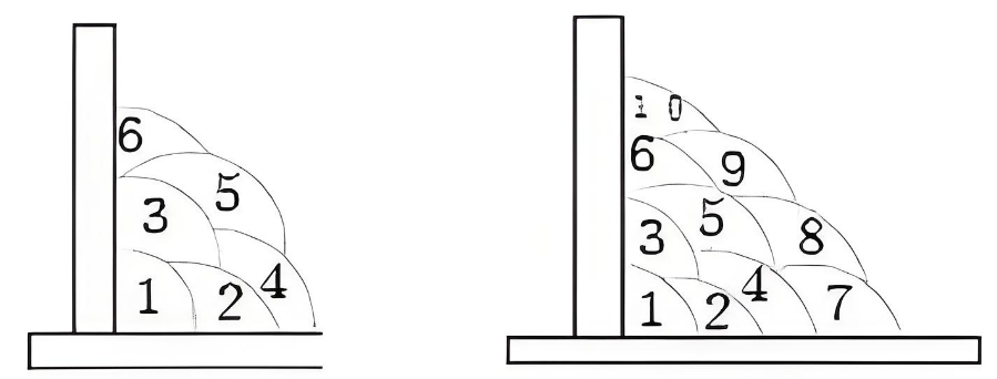
In multi-pass welding, each subsequent pass must overlap the previous pass by 1/2 to 2/3 of its width, to avoid grooves between beads that are too deep for subsequent welding to fuse into. If the surface of the previous layer is uneven, it must be ground with a wheel until the height variation is ≤ 1 mm before proceeding with the next pass.
5. Technology Frontier: From “Manual” to “Intelligent”
With the rapid development of sensors, AI, and robotics, multi-layer multi-pass welding of thick plates is progressively upgrading toward intelligence, significantly improving welding efficiency and quality consistency:
- Autonomous path planning: Advanced robotic systems can identify the actual groove dimensions in real time using laser vision and dynamically adjust the number of passes and welding parameters (current, weave amplitude, etc.); even when workpiece fit-up deviates, the system automatically compensates and generates collision-free welding paths, reducing manual intervention.
- Adaptive weld profile control: Neural-network-based predictive models can accurately predict weld profile results, controlling weld width error within ±0.3 mm and significantly improving the first-pass acceptance rate.
Conclusion
Multi-layer multi-pass welding of thick plates is a technology where “true knowledge comes from practice.” From precise groove design and strict interpass temperature control to the fine layout of every pass, every detail directly determines the final weld quality. Today, the welding industry is transforming from an experience-based craft that relied on individual skill into a systematic science that is data-driven and standards-controlled.