
Key Points for TIG Welding Operation
Tungsten inert gas (TIG) welding is a gas-shielded arc welding process with a non-consumable electrode. Argon is used as the shielding gas, and the arc established between the tungsten electrode and the workpiece melts the base metal and the filler wire to complete the weld.
Characteristics of TIG Welding
Excellent shielding performance: Argon is an inert gas that effectively isolates the weld from the air and prevents oxidation of the weld metal, making the process suitable for welding a wide range of metal materials.
Supports high current density welding: The arc heat is concentrated, which supports high current density welding and produces high-quality welded joints.
Visible arc: The welding process is visible, which facilitates weld pool observation and favors single-side welding with double-side weld formation.
Stable welding process: The arc burns steadily without spatter, and the weld bead is well formed.
Wide applicability: Suitable for all types of metals and all spatial welding positions, including ultra-thin workpieces.
Do Not Use DC Reverse Polarity
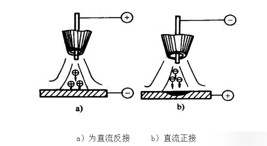
In DC TIG welding, the anode generates far more heat than the cathode. Therefore, with DC straight polarity (workpiece connected to the positive terminal), the tungsten electrode generates less heat and is less prone to overheating, allowing a larger current to be used with an electrode of the same diameter. In this case, the workpiece receives more heat, giving greater penetration and higher productivity; moreover, the thermionic emission capability of the tungsten electrode is stronger than that of the workpiece, keeping the arc stable and concentrated. For these reasons, DC straight polarity is recommended for most metals (except aluminum, magnesium, and their alloys). The situation is reversed with DC reverse polarity, which is generally not recommended.
Do Not Use Sharply Pointed Tungsten Electrodes
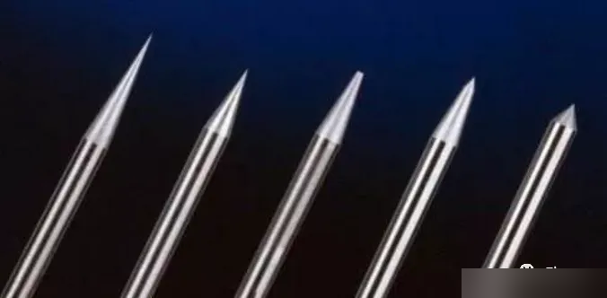
When a small-diameter sharply pointed tungsten electrode is used with a relatively high welding current, the current density becomes excessive, causing the electrode tip to overheat, melt, and burn off more rapidly. At the same time, the arc spot spreads onto the conical surface of the electrode tip, causing the arc column to expand noticeably and wander unsteadily, which adversely affects weld formation. Therefore, for high-current welding, a tungsten electrode of larger diameter should be used, and its tip should be ground to a blunt taper or a flat-topped conical shape.
Do Not Use Excessive Welding Speed
Welding speed is determined primarily by the workpiece thickness and must be coordinated with the welding current, preheat temperature, and other parameters to obtain the required penetration and bead width. In high-speed automatic welding, however, the effect of welding speed on gas shielding effectiveness must also be considered, and excessively high welding speeds should be avoided. If the welding speed is too high, the shielding gas stream is deflected strongly backward, and the tungsten electrode tip, arc column, and weld pool may be exposed to the air, degrading shielding performance.
Do Not Set the Gas Flow Rate Arbitrarily
The shielding gas for TIG welding is argon with a purity of 99.99%. When the welding current is 50–150 A, the argon flow rate should be 8–10 L/min; when the current is 150–250 A, the flow rate should be 12–15 L/min.
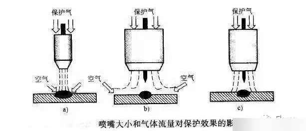
Under given conditions, there is an optimum combination range of gas flow rate and nozzle diameter. For manual TIG welding, a flow rate of 5–25 L/min corresponds to a nozzle bore of 5–20 mm. Outside this range, if the flow rate is too low or the nozzle bore too large, the gas stream lacks stiffness and its ability to displace the surrounding air is weak, resulting in poor shielding; if the flow rate is too high or the nozzle bore too small, the high gas velocity creates turbulence, which not only narrows the shielding zone but also draws in air, reducing shielding effectiveness.
Do Not Set the Nozzle-to-Workpiece Distance Arbitrarily
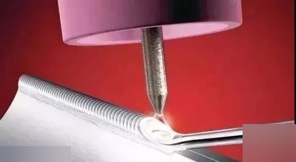
The nozzle-to-workpiece distance reflects the relative lengths of the electrode extension and the arc. With a constant electrode extension, changing the nozzle-to-workpiece distance alters both the arc length and the gas shielding condition.
If the nozzle-to-workpiece distance is increased, the conical base of the arc becomes larger and gas shielding effectiveness is significantly affected. If the distance is too small, however, the operator’s view is obstructed and the tungsten electrode may easily contact the weld pool, causing tungsten inclusions. The recommended electrode extension beyond the nozzle is 4–5 mm; it should be 2–3 mm in positions with poor shielding, such as fillet welds, and 5–6 mm in deep grooves. In general, the distance between the nozzle tip and the workpiece should be 8–14 mm and should not exceed 15 mm.
Do Not Adjust the Cleaning Action Arbitrarily
Square-wave AC TIG welding can suppress the DC component and adjust the strength of cathodic cleaning by changing the ratio of the conducting times of the positive and negative half-cycles. However, the appropriate minimum ratio should be selected according to the welding conditions so that it both satisfies the need to remove the oxide film and achieves maximum penetration with minimum tungsten electrode wear. Although an excessively large ratio provides stronger cathodic cleaning, it causes severe electrode burnout and produces a shallow, wide weld pool, which is detrimental to welding.
Do Not Move the Torch Arbitrarily
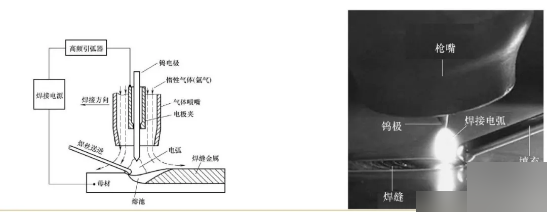
Flat position welding is one of the easier welding positions to master and is suitable for both manual and automatic welding. During welding, the position of the tungsten electrode relative to the workpiece must be accurate and the torch angle appropriate. Particular attention should be paid to arc stability and the uniformity of torch travel speed to ensure consistent penetration and bead width. In manual welding, the forehand (leftward) technique is recommended, with the torch moving in a uniform straight line. To obtain a wider bead, lateral oscillation of the torch is permissible, but jerky movement should be avoided. The filler wire diameter generally should not exceed 3 mm.
Do Not Use Aluminum or Copper Filler Wire (Hot Wire Process)
In hot wire welding, an auxiliary power source generates resistance heat in the front section of the filler wire, preheating the wire to a preset temperature and thereby increasing the deposition rate. For aluminum and copper, however, the low resistivity demands a very large heating power source, which causes excessive arc magnetic blow and non-uniform melting. Therefore, aluminum and copper filler wires are not suitable for hot wire welding.
Practical Tips
The quality of TIG welds essentially depends on three factors: shielding gas, heat input, and power source stability.
-
Check the condition of the power source. Before welding, check the gas flow rate to ensure that the gas is delivered evenly and that shielding is stable and timely.
-
Control the heat input. Match the welding current, voltage, and travel speed to the base material and plate thickness. For large weld beads, use multi-layer multi-pass welding and control the interpass temperature to prevent high-temperature oxidation of the weld.
-
Set post-flow on the power source to 0.5–5 s. After the arc is extinguished, do not withdraw the torch immediately; keep it in place while the post-flow gas continues to shield the weld.
-
Use pre-flow. Before welding, enable the pre-flow function and set it to 10 s so that argon protects the weld zone in advance.
-
Check the gas purity. Try replacing the argon cylinder with a fresh one to test.
-
Check for gas leaks. Seal the ceramic nozzle with your hand, release it after 5 seconds, and check whether pressure is maintained.
-
Check tungsten electrode quality. Poor electrode quality can also degrade weld quality; it is advisable to use tungsten electrodes from reputable brands with reliable quality.
Conclusion
TIG welding is a high-quality welding process, but the eight precautions described above must be observed during operation; doing so can effectively improve the quality and efficiency of TIG welding.