Hydraulic Welding Positioner EWP-3T: 3,000 kg Lift, Tilt and 360° Rotation
The EWP-3T is a three-axis hydraulic welding positioner rated for workpieces up to 3,000 kg. It combines three independent motions — hydraulic lift, powered tilt and continuous 360° table rotation — so that heavy, awkward weldments can be presented to the welder (or to a welding robot) in the flat, downhand position, where deposition rate, penetration consistency and bead appearance are at their best. Height, angle and rotation speed are all adjustable, and the lift is infinitely variable through a hydraulic cylinder rather than a fixed set of mechanical steps.
It is one of the machines DESAN ELECTRIC supplies to fabricators worldwide — the positioner range is built under the BIQEE brand, welding turning rolls under DESAN and combination welding machines under ZAULUX, all quoted and delivered by DESAN ELECTRIC LTD.
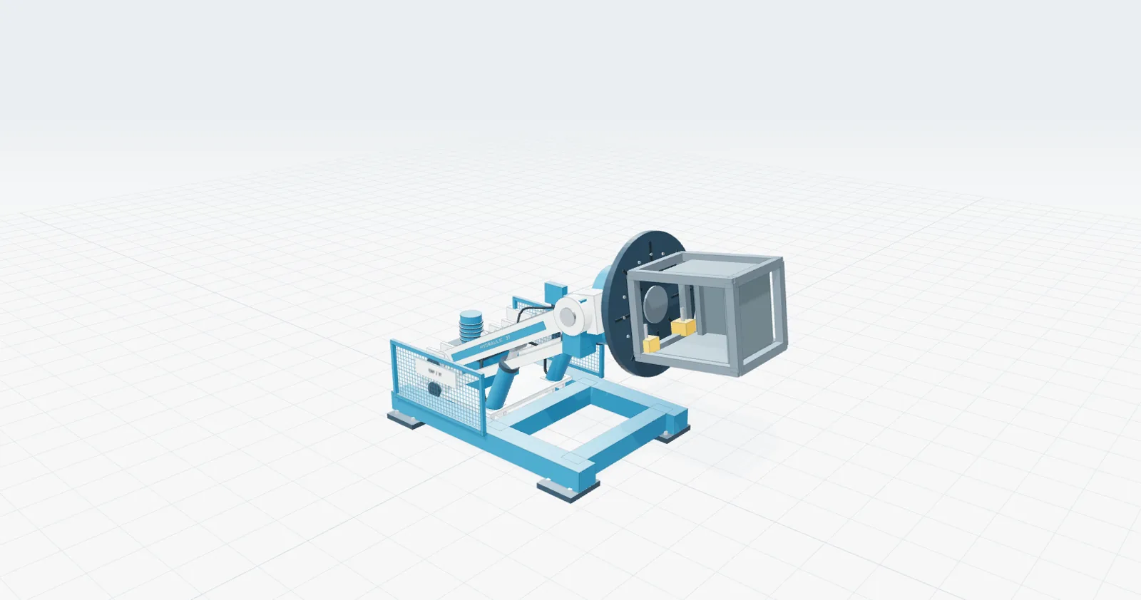
EWP-3T hydraulic welding positioner — hydraulic lift, powered tilt, 360° table rotation, 3,000 kg class.
Positioners in this load class are used wherever large cylindrical or prismatic workpieces have to be turned and re-presented dozens of times per shift: oil & gas and petrochemical fabrication, pressure vessels and boilers, wind-tower and flange production, shipbuilding, railway and heavy general fabrication.
Three Motions, One Fixture
1. Hydraulic lift — the workpiece comes to the operator
A hydraulic cylinder raises and lowers the headstock so the weld joint sits at the operator’s comfortable working height. Because the lift is infinitely variable, the same machine serves a small flange and a two-metre shell without shimming, staging or re-slinging between passes. In the EWP-3T motion study the headstock centre travels to approximately 2,493 mm, with the lift arm running from 14° (low position) to 52° (high position).
2. Powered tilt — turning vertical joints into downhand welds
Tilting range is -45° to +135°. On a cylindrical shell this means a circumferential seam, a dished end or a nozzle joint can be brought into the flat position instead of being welded vertically or overhead. Less operator fatigue, higher travel speed, and a weld pool that behaves predictably are the direct result.
3. Continuous table rotation — one pass instead of many
The power-rotated table runs at 0.05 – 0.5 rpm, steplessly adjustable. For circumferential work the arc stays on: instead of stop-start welding with repositioning between segments, the workpiece rotates at a constant surface speed under the torch — the usual route to uniform weld thickness on shells, tube sheets and rings.
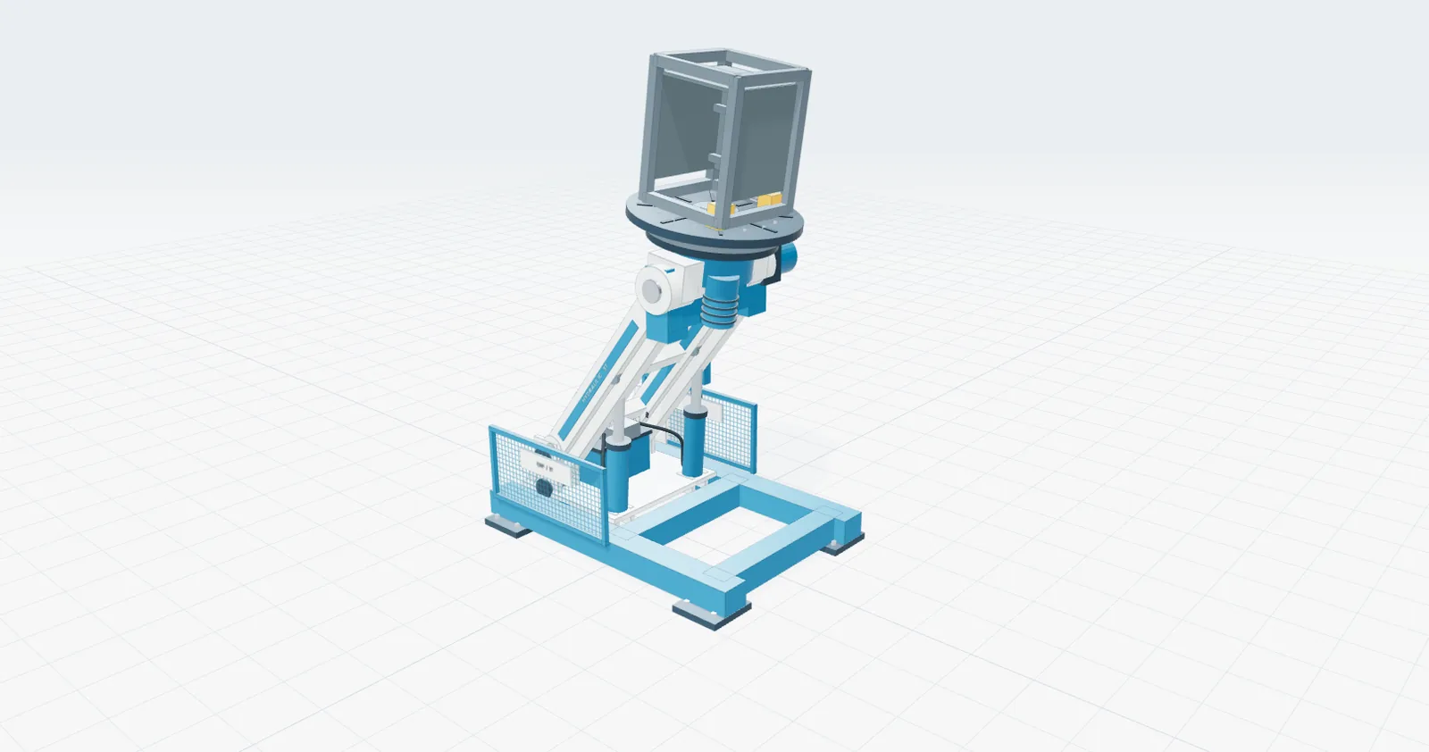
Workpiece at height and tilted: the hydraulic cylinder carries the load while the table drive turns it.
Design and Construction
The machine is a three-part system, supplied as one package:
- Main body — fabricated heavy-gauge steel base and elevating column with machined load-bearing surfaces. The base frame measures approximately 2,800 × 1,900 mm, which is what gives a 3-tonne eccentric load its stability.
- Hydraulic system — cylinder and power unit providing the infinitely variable lift; the concept study shows 541 mm of cylinder extension from the low position to the working pose.
- Electric control system — one control panel, one remote pendant and a foot switch, so the operator can jog the table, tilt and lift from the weld station instead of walking back to a cabinet.
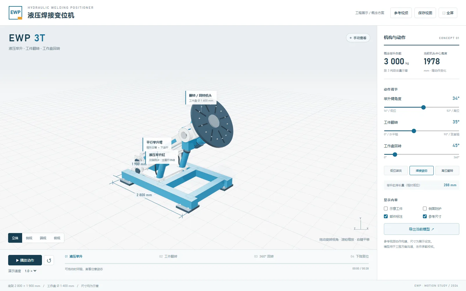
Mechanism view: base frame, hydraulic lift cylinder, tilting head and Ø1,400 mm worktable.
Motion Range at a Glance
| Parameter | Value | Note |
|---|---|---|
| Rated lifting load | 3,000 kg | 3-tonne class, centre of gravity within the rated G/E envelope |
| Worktable diameter | Ø1,400 mm | radial mounting slots for clamps and fixtures |
| Base frame | ≈2,800 × 1,900 mm | freestanding, floor-mounted |
| Lift arm angle | 14° (low) → 52° (high) | stepless |
| Worktable centre height | up to ≈2,493 mm | varies with lift arm angle |
| Workpiece tilt | 0° (horizontal) → 82°–90° (vertical) | tilt range -45° to +135° |
| Table rotation | 0° – 360°, continuous | 0.05 – 0.5 rpm, stepless |
| Lift cylinder stroke (from low position) | ≈541 mm | concept motion study value |
Figures above are taken from the EWP-3T motion study (engineering concept). Confirm final values against the drawing package issued with your order.
Technical Parameters — EWP-3T, 3,000 kg Class
| Parameter | EWP-3T (3,000 kg) |
|---|---|
| Maximum load | 3,000 kg |
| Gravity distance (G) | 300 mm |
| Eccentric distance (E) | 200 mm |
| Rotation speed | 0.05 – 0.5 rpm (stepless) |
| Tilting range | -45° to +135° |
| Table diameter | Ø1,400 mm |
The hydraulic positioner family
The same hydraulic lift / tilt / rotate architecture is built in stepped load classes, so a fabricator can standardise on one control philosophy from small fabrication to very heavy shells:
| Model | Max. load | Gravity distance (G) | Eccentric distance (E) | Rotating speed | Tilting range | Table diameter |
|---|---|---|---|---|---|---|
| HYD-06 | 600 kg | 250 mm | 200 mm | 0.1 – 1 rpm | -45° – +135° | 900 mm |
| HYD-10 | 1,000 kg | 250 mm | 200 mm | 0.1 – 1 rpm | -45° – +135° | 900 mm |
| HYD-30 / EWP-3T | 3,000 kg | 300 mm | 200 mm | 0.05 – 0.5 rpm | -45° – +135° | 1,400 mm |
| HYD-50 | 5,000 kg | 300 mm | 200 mm | 0.05 – 0.5 rpm | -45° – +120° | 1,500 mm |
Above the 5,000 kg class the same hydraulic architecture continues with larger tables and heavier base frames; those machines are sized per workpiece rather than picked from a list. Smaller classes, longer tables and custom table tops are built to order — tell us the workpiece mass, its centre of gravity and the table diameter you need, and the machine is sized around it. See the welding positioner range for the standard WP series.
Choosing the Size: Centre of Gravity (G) and Eccentricity (E)
Rated load on its own does not size a positioner. Two distances decide whether the machine will hold your workpiece and turn it safely:
- Gravity distance (G) — the distance from the table centre to the workpiece’s centre of gravity, measured along the table axis. A workpiece whose mass sits far above the table face loads the tilting mechanism with far more torque than one bolted flat.
- Eccentric distance (E) — the radial offset of the centre of gravity from the table centreline. This is the load that pushes the table drive, the bearing and the base frame sideways.
Both must be evaluated including chucks, fixtures and clamping plates, not just the part. When either distance exceeds the published figure for the model, step up one load class — it is cheaper than a machine that will not tilt a fully loaded shell.
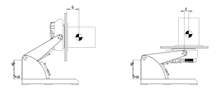
G (centre of gravity above the table face) and E (radial eccentricity) — the two distances that size a positioner.
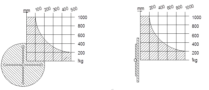
Load class against table diameter: capacity and table size move together.
Scope of Delivery
- 1 × main body (base frame, elevating column, tilting head, rotating worktable)
- 1 × hydraulic system (cylinder and power unit)
- 1 × electric control system comprising: control panel, remote pendant, foot switch
Applications
- Pressure vessels and boilers — shells, dished ends, nozzles and tube sheets turned to downhand position.
- Wind power — tower sections, flanges and ring welds rotated at constant surface speed.
- Oil & gas / petrochemical — pipe spools, separators and skid-mounted fabrications.
- Shipbuilding and offshore — hull blocks, foundations and structural assemblies.
- Heavy general fabrication — any weldment where the operator would otherwise be welding out of position or chasing the arc around a part.
The positioner also serves as the workpiece axis of an automated cell: the robotic partner shown here is a FANUC M-20iA/20 with a 20 kg payload mounted on a common base, which gives the cell a 3,000 kg workpiece axis under a light-payload arc arm. In a robotic cell the positioner’s rotation becomes a coordinated external axis — the robot holds the torch, the positioner indexes the part, and the operator stays out of the arc.
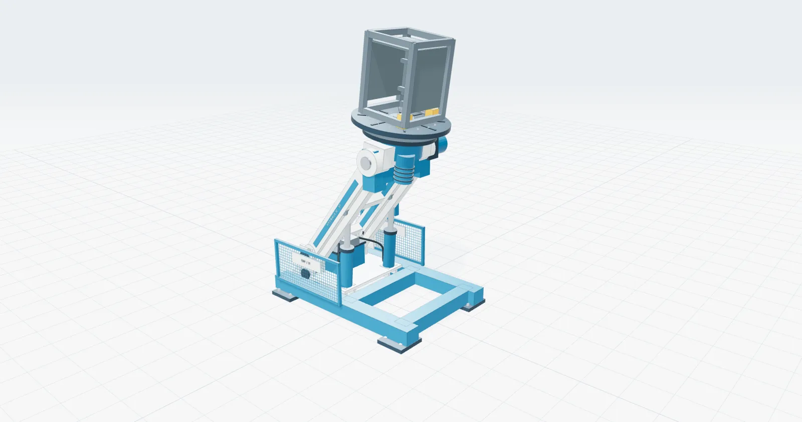
Automated cell concept: 20 kg robot arm on a 3,000 kg hydraulic positioner — workpiece axis and torch axis working together.
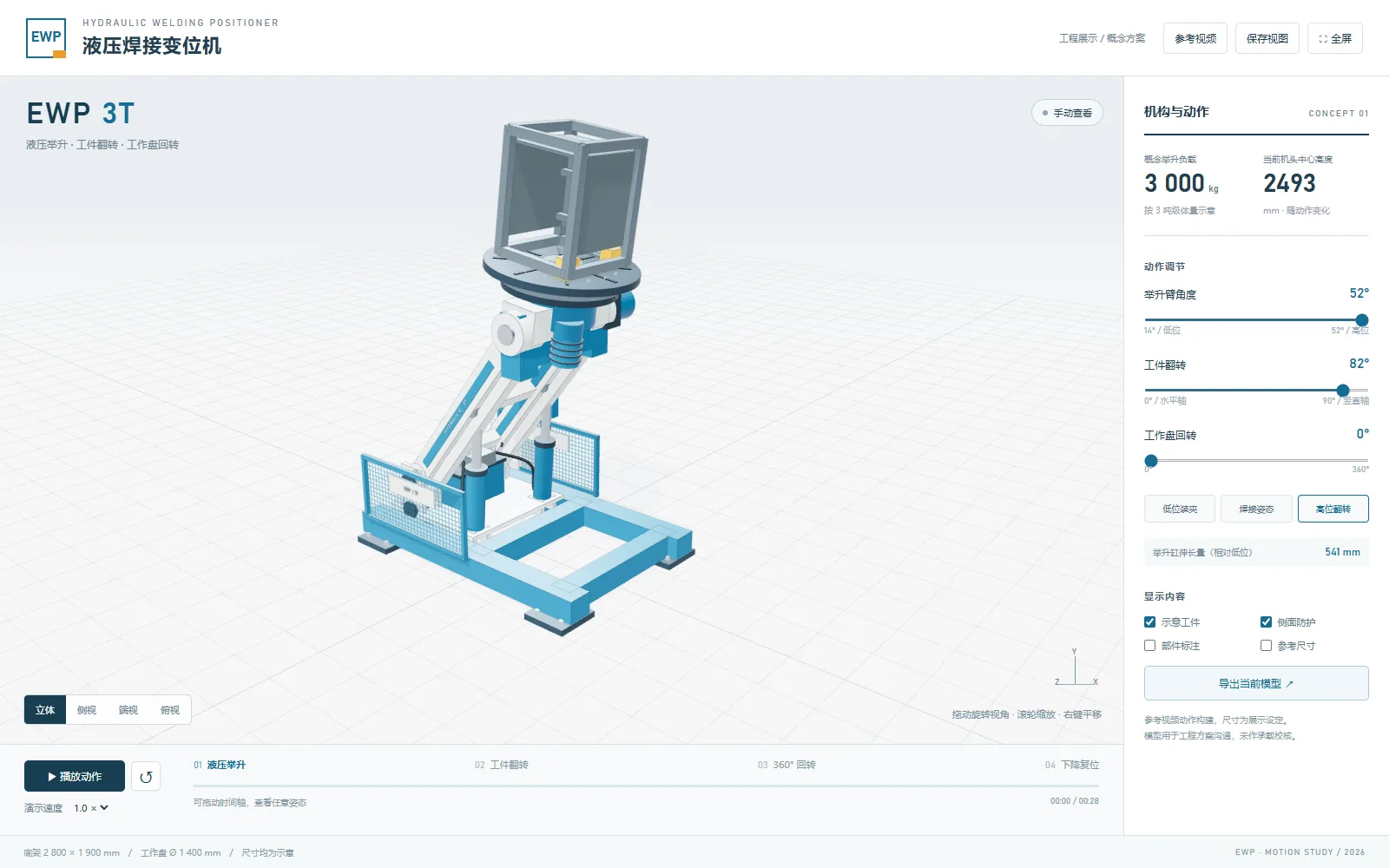
Motion study used to size the hydraulic cylinder and confirm the tilt/rotation envelope before manufacture.
In Our Own Workshop
The hydraulic tilting positioners we build are the same architecture, scaled: the photographs below show a 15-tonne class machine in the workshop, with the worktable carried on the hydraulic tilting frame.
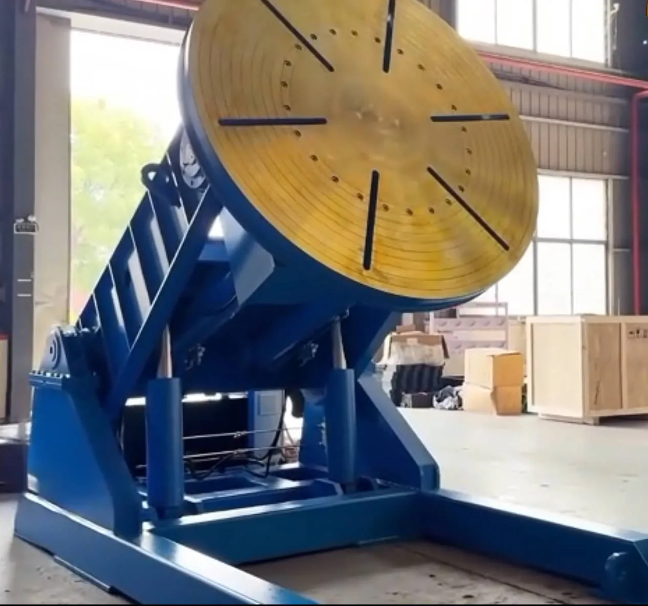
15-tonne class hydraulic tilting positioner — worktable tilted on the hydraulic frame.
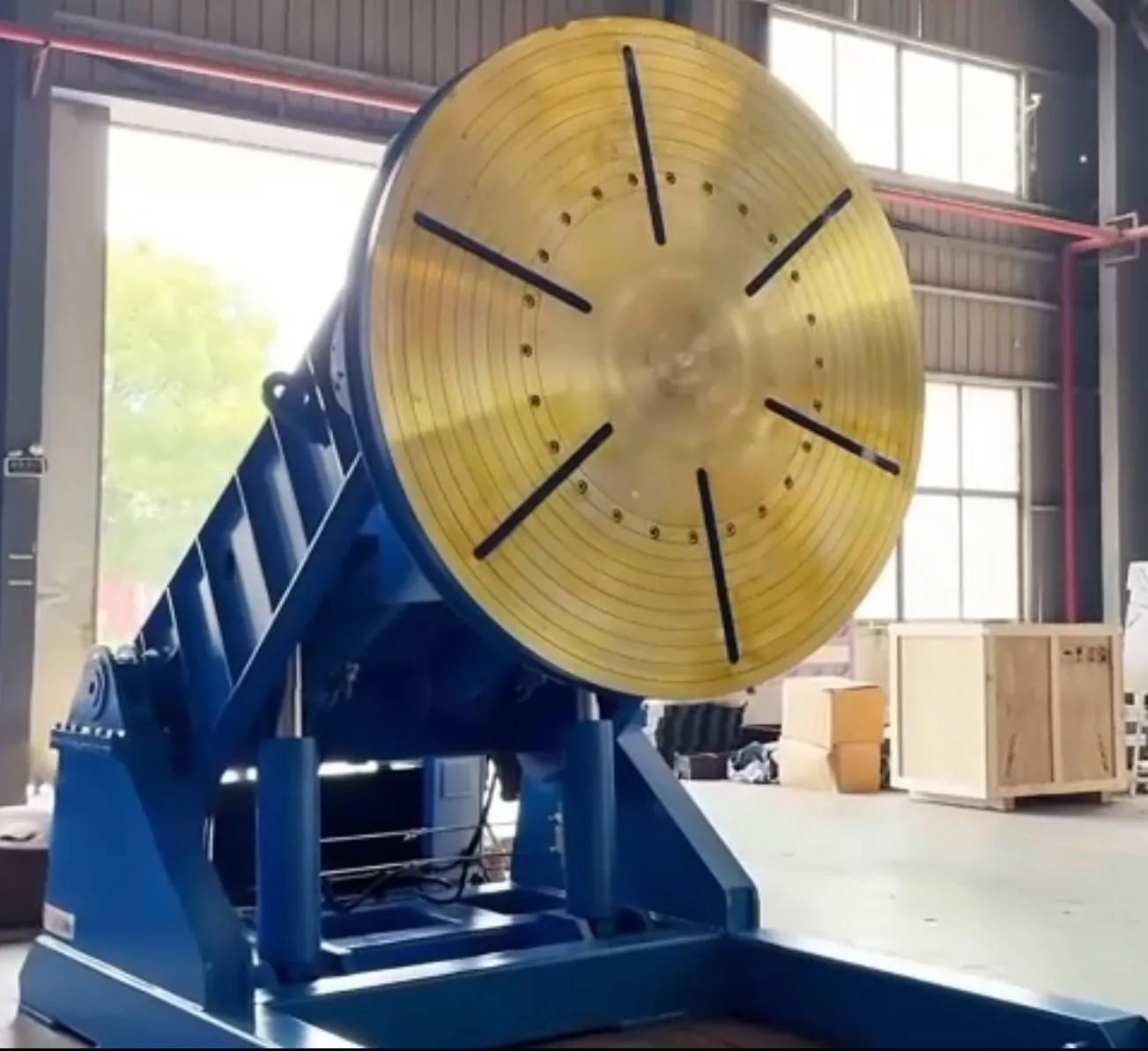
Same family, larger class: the tilting frame carries a worktable sized for full vessel sections.
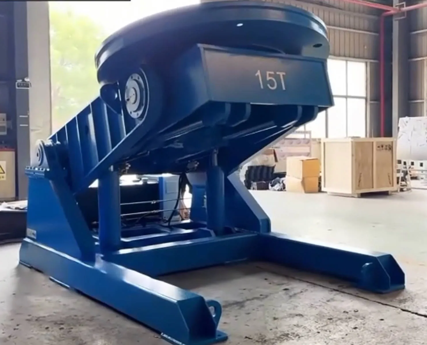
Floor-level view of the tilting frame and base — the load path from table to floor is entirely through the fabricated base.
Frequently Asked Questions
Can the EWP-3T weld automatically, not just position?
Yes. The table and tilt axes can be used as a powered workpiece axis under a welding robot or a column-and-boom welder, with the positioner indexing between weld passes or rotating continuously during circumferential welding.
How do I know whether a 3,000 kg machine is enough?
Check the workpiece mass and its gravity distance and eccentricity, with fixtures included. If either distance exceeds 300 mm (G) or 200 mm (E) on the 3-tonne class, the next class up is the correct answer.
Why hydraulic rather than a mechanical lift?
A hydraulic cylinder gives infinitely variable height with smooth, jitter-free travel, and it holds position under load without a mechanical ratchet or screw. It also keeps the machine compact for the load it carries.
How is the machine controlled?
From the control panel, a remote pendant, or a foot switch — lift, tilt and rotation each have their own command, so the operator can jog the part while standing at the joint.
Do you build sizes other than 3,000 kg?
The hydraulic family runs from 600 kg to well above 20 tonnes, with table diameters from 900 mm to 2,000 mm and beyond, and machines are configured around the workpiece rather than the other way round.
Size Your Positioner With an Engineer
Send us the workpiece mass, its centre-of-gravity distance (G) and eccentricity (E), the table diameter you need, and whether the machine will be used under a robot or by hand. We will come back with the correct load class, the motion envelope, and the delivery scope — contact our engineering team or email estra@desanee.cn.