
When the work is bigger than the robot
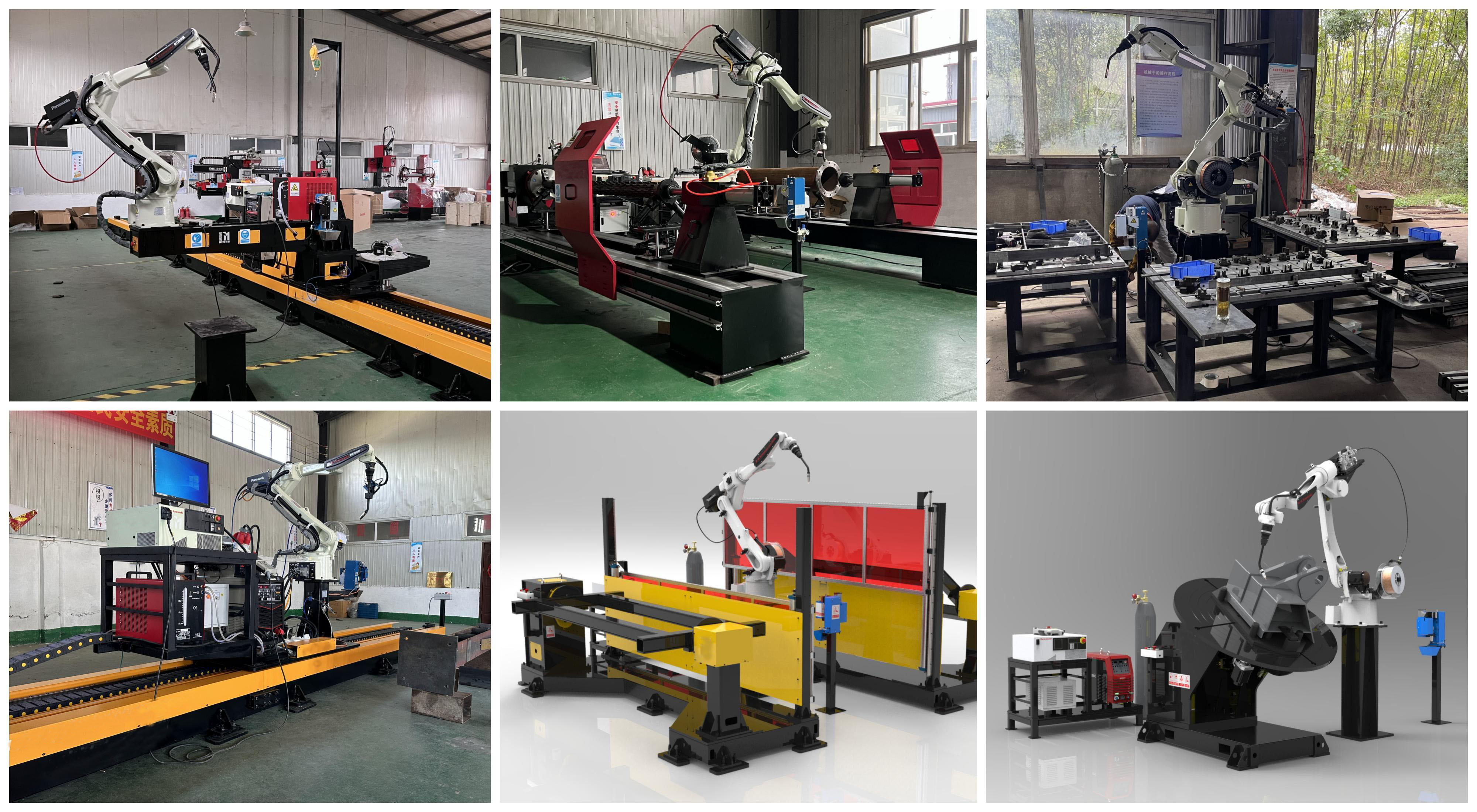
A fixed six-axis welding robot has a working envelope measured in a couple of metres. That is ample for a bracket or a sub-assembly, and useless for a 12 m excavator boom, a truck chassis rail or a structural frame that has to be welded at eight stations along its length. The usual answer is to move the robot instead of the part: mount it on a travelling carriage or a gantry that spans the work area, and the cell's reach becomes a function of rail length rather than of robot size.
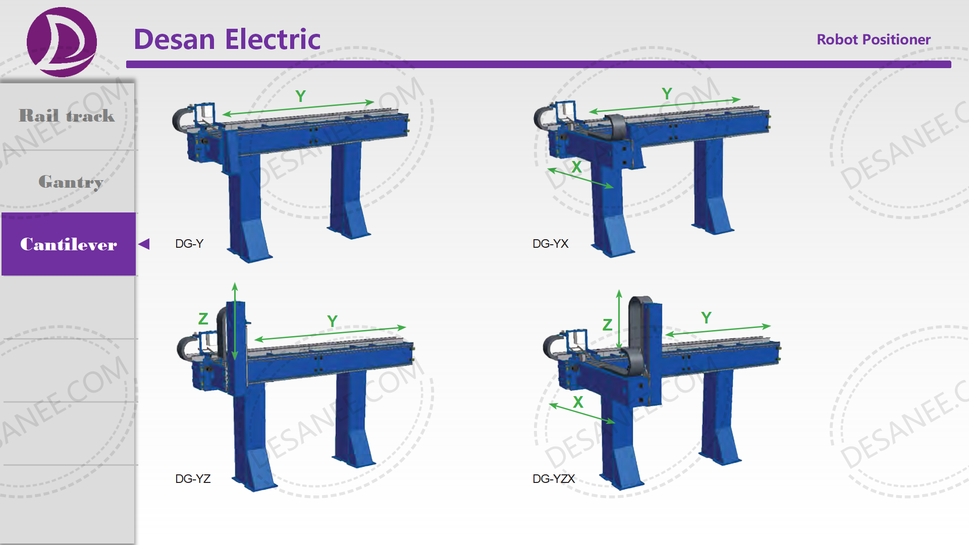
The GR40 is a gantry robot welding system built on that principle — a 6-axis welding robot carried on an overhead or floor-mounted gantry with one or more linear travel axes. The workpiece stays on a fixed bed or on positioners, and the robot travels to each seam in turn.
Gantry versus fixed robot versus robot on a track
| Configuration | Reach | Floor space | Access for loading | Best for |
|---|---|---|---|---|
| Fixed robot + positioner | Robot envelope only | Compact | Part must be brought to the cell | Small to medium parts in high volume |
| Robot on a floor track | Track length × envelope | Track occupies the bay | Open — crane access from above | Long parts, two or three stations on one rail |
| Overhead gantry | Spans the bay in two directions | None at floor level | Best — the floor is free for cranes and forklifts | Very large assemblies, multi-station welding |
| Portal / bridge gantry | Two linear axes plus robot | Requires two rails and structure | Good, but rails constrain crane paths | Wide parts, multiple seams in different planes |
The decisive argument is usually floor access rather than reach. In a fabrication bay the same floor has to serve cranes, forklifts, fit-up benches and inspection. An overhead gantry keeps the robot out of that traffic; a floor track puts a rail exactly where a forklift wants to be.
Seam finding, not just seam following
On a large fabricated assembly the joint is never exactly where the drawing says it is. Fit-up tolerance on a 10 m weldment accumulates well beyond the accuracy of a teach-and-repeat programme, which is why gantry cells are almost always specified with sensing. Two technologies do the work:
- Laser or camera seam tracking — the sensor looks ahead of the arc, measures the joint position and offset, and corrects the path in real time. This handles variation along a single seam.
- Touch sensing / seam searching — the robot touches the workpiece at several points to establish where the part actually is, then shifts the whole programmed path to match. This handles part-to-part variation between workpieces.
Both are worth having together: touch sensing finds the part, laser tracking follows the joint once welding starts. Specifying only one is a common and expensive omission.
The economics that decide the project
Gantry cells are capital-intensive, so the justification has to be arithmetic rather than enthusiasm. Three numbers dominate:
- Arc-on time. A manual welder on a large fabrication typically achieves 20–35% arc-on time; the rest goes on repositioning, chipping, measuring and fetching. A gantry cell with good fixture access can reach 60–80%. That ratio — not the robot's travel speed — is where the saving comes from.
- Rework rate. Consistency is the second saving. A cell that holds the same torch angle, travel speed and stick-out on every part reduces repair and re-inspection, which on a coded weldment is often the larger cost.
- Batch size against fixture cost. A gantry cell pays back on part families, not single parts. If the same assembly repeats fewer than a few dozen times a year, the fixture engineering will not amortise and a manual positioner with a good operator is the better investment.
Applications
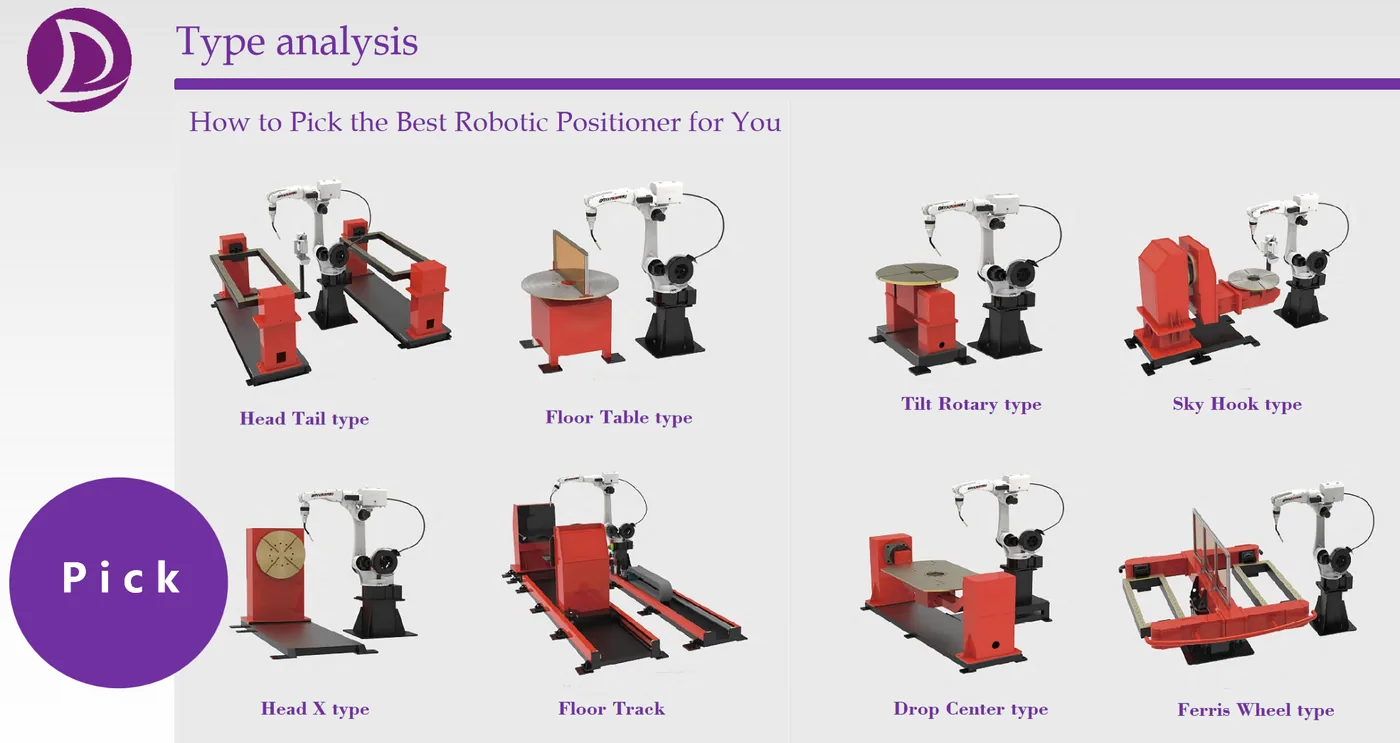
- Engineering machinery — excavator booms and arms, loader frames, crane sections.
- Transport equipment — chassis rails, trailer frames, rail vehicle underframes.
- Construction steel — fabricated columns and trusses welded at multiple stations.
- Wind power — tower internals, nacelle frames and foundation components.
Specifying a GR40 cell
A gantry cell is designed around the part family and the bay, so the useful starting information is: the largest and smallest parts with drawings, total weld length per part and the number of seams at different orientations, required cycle time, part weight and how it is loaded, the available bay dimensions and crane capacity, and the weld quality standard the finished part must meet. From that we specify rail length, gantry span, robot model, travel drives, sensing package, fixturing and guarding.
The GR series covers 6-axis robot configurations with optional single or dual gantry travel axes. Minimum order quantity is 1 set; robot cells are quoted per project. Standard systems ship in 30–50 days after deposit, with integrated cells scheduled in the technical proposal. Payment terms are T/T; trade terms are FOB, FCA or CIF. Core ranges are CE compliant and supplied against a certificate of compliance, with guarding and risk-assessment documentation for the installed cell.
DESAN ELECTRIC LTD supplies robot welding systems under the DESAN and BIQEE brands and handles every enquiry, quotation and contract directly. The company has served 1,000+ customers in 20+ countries over 20+ years, with welding engineering experience dating from 1997.