
What a box beam build-up line actually does
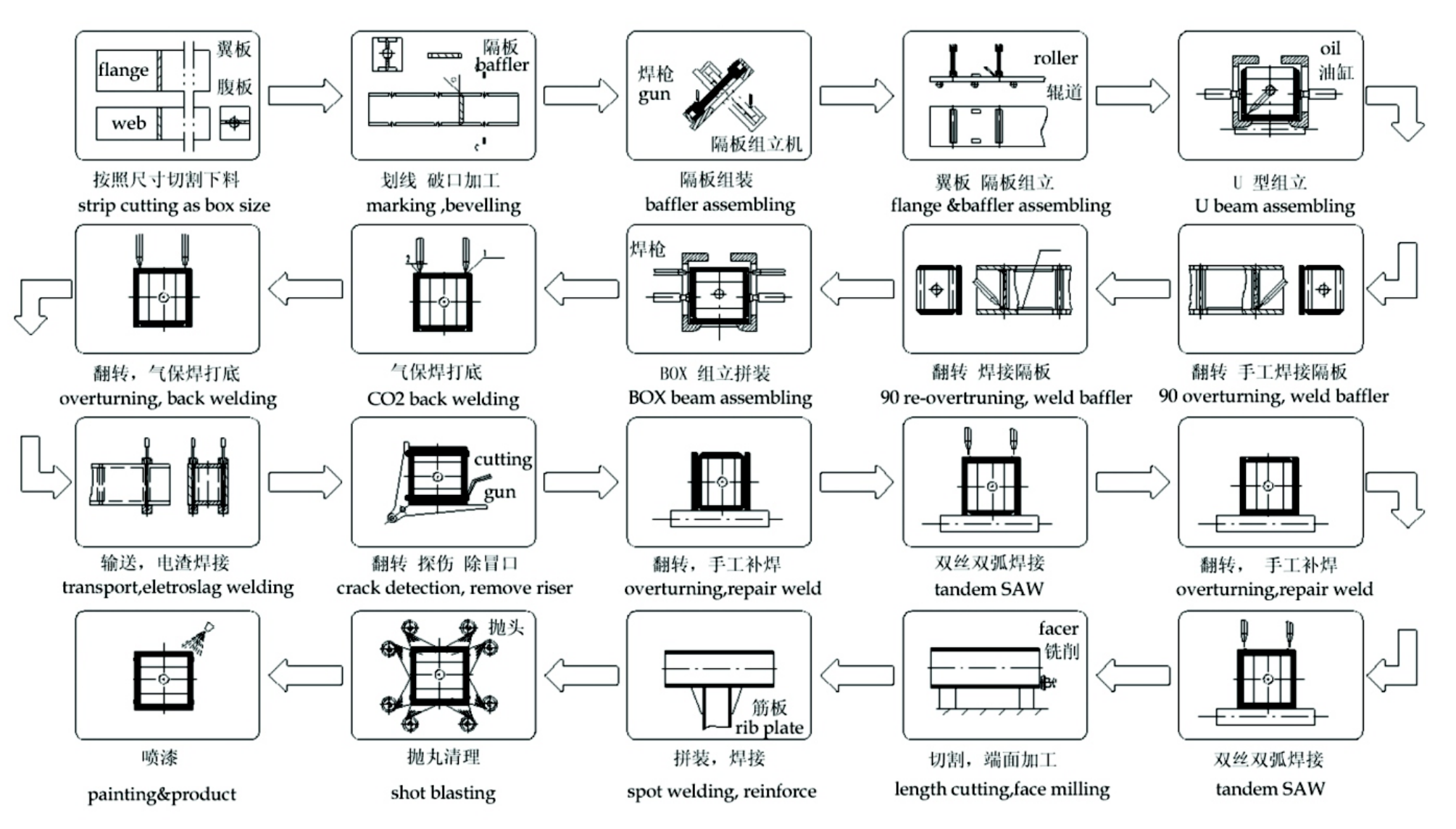
A box beam is four plates welded into a closed rectangular section: two webs, two flanges and, in most structural specifications, internal diaphragms at intervals along the length. Turning that from loose plate into a straight, in-tolerance column is a sequence of positioning jobs, not a single weld — plate edge preparation, web-and-flange assembly and tacking, internal diaphragm fit-up, main seam welding, and straightening after the shrinkage has moved the section.
The GZJ12 and UBZ12 are two configurations of the same production line concept: a gantry or portal frame carrying the welding heads, a bed of roller conveyors or powered carriages that moves the box through the stations, and a control system that holds the sequence. GZJ12 is configured for the assembly-and-welding route on heavier sections; UBZ12 is the welding-beam build-up variant used where the same line has to run a narrower range of sections at higher throughput. Which one suits a shop depends on section size range, throughput and how much of the fit-up work is manual.
The five stations in the line
1. Plate edge preparation
Box sections are welded from the outside with deep penetration, and the flange edges normally need a bevel so the weld reaches the web root. Edge milling or beveling ahead of the line keeps the groove consistent, which in turn keeps the welding parameters consistent. A line that receives plate with hand-ground edges will never hold a stable weld profile — this station is the one most often cut from a budget and most often regretted.
2. Web and flange assembly with hydraulic clamping
The four plates are brought together square and clamped before anything is welded. Squareness here is what decides the final straightness: a 12 m box assembled 2 mm out of square will be metres out of tolerance after welding, and no amount of straightening will bring it back. Hydraulic clamping rams close the assembly to the nominal section and hold it while the tack welds are placed.
3. Internal diaphragm fit-up
Diaphragms stiffen the section and transfer load between flanges. They must be positioned within tolerance along the length and must not be welded in a way that leaves the web distorted. On most lines this is a manual station; the line's job is to present the open box at a comfortable working height so the fitter can work standing rather than crouching inside the section.
4. Main seam welding
With the box assembled, the four longitudinal seams are welded. The gantry carries either submerged-arc heads or, on thick-web sections, electro-slag heads that weld the vertical web-to-flange joint in a single pass. The choice is a thickness decision: below roughly 60 mm, submerged arc with multiple passes is more controllable and gives a better as-welded microstructure; above that, electro-slag or electro-gas becomes the economical route. The line's control system tracks the seam and keeps the head at the correct angle and distance while the carriage advances.
5. Straightening
Welding shrinks. A box column with four full-length seams will bow, and the bow is predictable in direction and roughly proportional to weld volume and section stiffness. A straightening station — mechanical, flame or a combination — brings the section back inside the camber and straightness tolerance the specification asks for. Skipping this station is the second most common line-omission mistake, and it shows up as rejected columns at the buyer's inspection, not at the fabricator's.
Line layout decisions that decide throughput
| Decision | Option A | Option B | Effect |
|---|---|---|---|
| Box transport | Roller conveyor bed | Powered rail carriages | Roller bed is faster to install and cheaper; carriages handle longer and heavier sections with less floor space |
| Welding travel | Fixed box, moving gantry | Moving box, fixed heads | Moving gantry suits long sections in a narrow bay; moving box suits short sections at high repetition |
| Seam orientation | Box rotated to flat position | Heads follow vertical seams | Flat position gives better bead shape; vertical seams remove the rotation time |
| Station count | Single-station line | Multi-station line | Multi-station separates fit-up from welding and roughly doubles output for the same floor area |
Box beam applications
Welded box sections carry load in two directions at once, which is why they appear wherever a structure has to resist torsion as well as bending:
- High-rise and long-span construction — columns, transfer beams and roof trusses.
- Bridges — box girders and arch ribs, where a closed section resists both bending and lateral-torsional buckling.
- Crane runway beams and crane girders — where fatigue performance over millions of cycles depends on weld toe geometry.
- Heavy machinery bases and press frames — where stiffness per unit weight matters more than cost per metre.
Technical data: GZ12 baffle assembly, UBZ12 assembly and XD12 electro-slag stations
The GZJ12 / UBZ12 line is specified station by station. The figures below are the station-level parameters that decide whether a line suits a particular beam range — they are the numbers to check against the section list before anything else is discussed.
GZ12 baffle (stiffener) assembly machine
The GZ12 assembles and tacks the internal baffles into the box before the closing flange goes on. Cylinders clamp the baffle in position, the tacks are placed, and the worktable then turns 180° so the second face can be welded. A worm-gear drive with an electromagnetic brake holds the table at any angle with self-locking, and the turnover is foot-switch controlled.
| Parameter | Value |
|---|---|
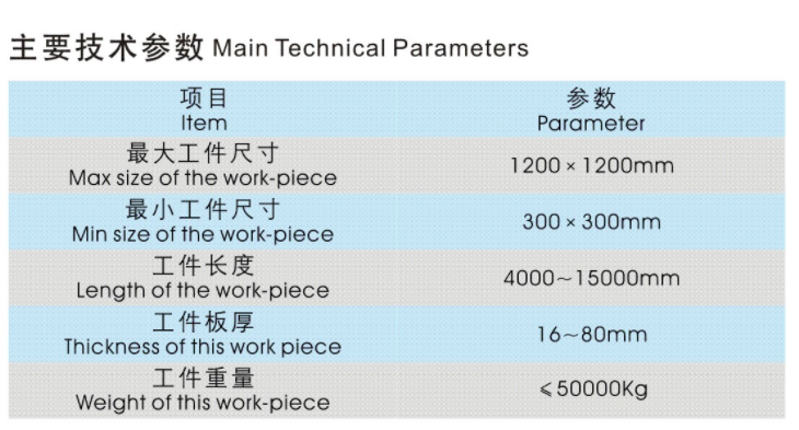
| Workpiece dimension | 300 – 1,200 mm |
| Baffle thickness | ≤ 80 mm |
| Turnover motor power | 0.75 kW |
| Turnover speed | 1 rpm |
| Worktable load capacity | 1,500 kg |
| Height of rotation centre | 1,000 mm |
| Turnover angle | ±180° |
UBZ12 assembly machine
A gantry frame carries all the clamping devices; two motors on the moving beam drive wheels along a standard 38 kg/m heavy track through worm and rack reducers. The two parallel tracks are tied together by a high-strength drag bar specifically so the track cannot splay apart under the reaction of the left and right cylinders — that splay is what ruins assembly squareness on a line built without it. Rollgangs turn on a cycloid reducer through chain drive and carry the workpiece into and out of the station.
| Parameter | Value |
|---|---|
| Workpiece dimension | 300 – 1,200 mm |
| Workpiece length | 4,000 – 15,000 mm |
| Max load capacity | 20 t |
| Gantry moving speed | 4 m/min / 6 m/min |
| Hydraulic system pressure | 14 MPa |
| Left/right cylinder max force | 15 t |
| Upper cylinder force | 30 t |
| Left/right cylinder max stroke | 800 mm |
| Upper cylinder max stroke | 900 mm |
| Gantry moving motor | 0.85 / 1.1 kW × 2 |
| Oil pump motor | 11 kW |
| Rollgang motor | 2.2 kW |
| Rollgang conveying speed | 9.3 m/min |
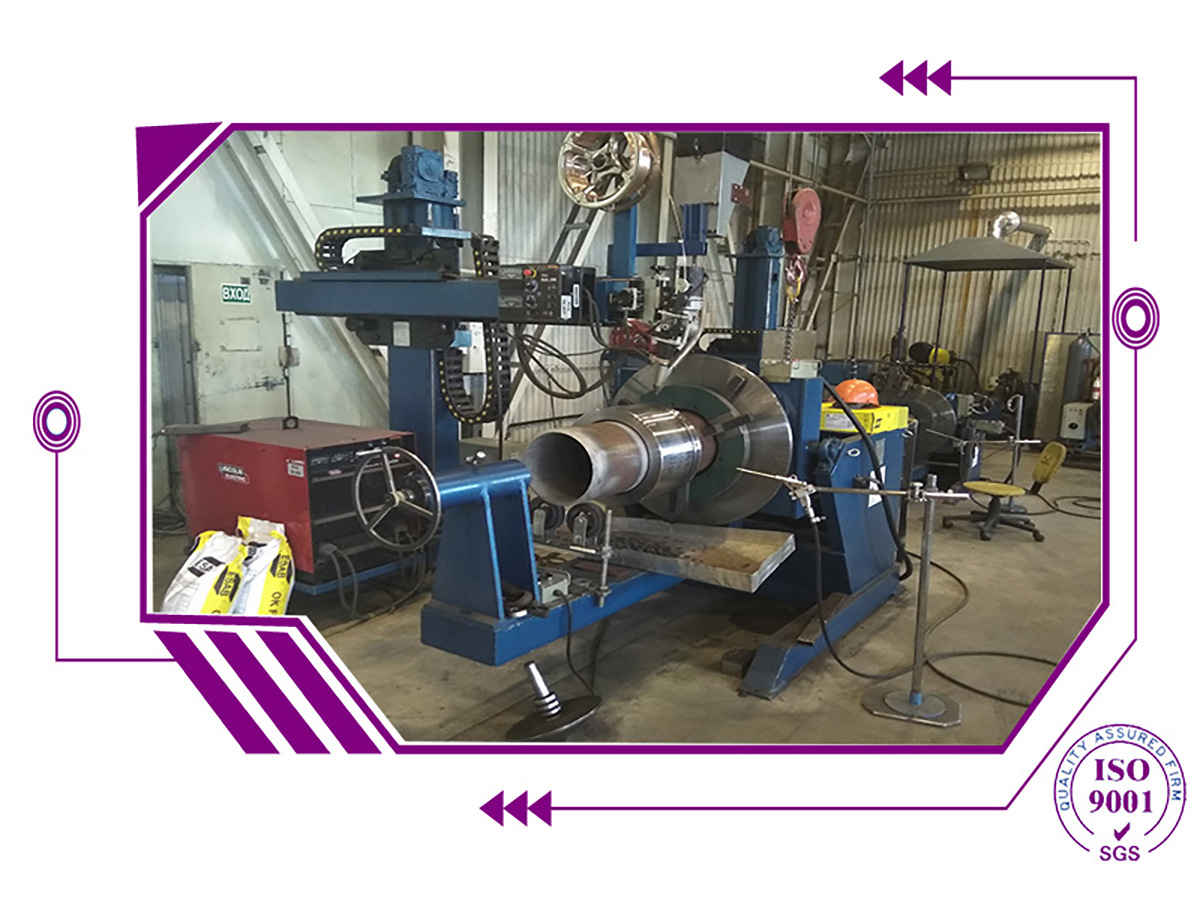
XD12 column-boom electro-slag welding station
The XD12 station exists because of a deliberate design decision upstream: when the baffle is assembled, a clearance is left between baffle and box so the baffle can be positioned. The box then feeds on the rollgang to the vertical frame and the electro-slag head welds that clearance closed. The column frame — which carries the welding head and keeps it aimed at the weld hole — travels along the length of the beam on a motor-driven cart through a speed reducer.
| Parameter | Value |
|---|---|
| Welding power source | Lincoln DC-600 × 2 |
| Head configuration | Vertical electro-slag head on travelling column frame |
| Travel | Along beam length, AC motor via speed reducer |
The twin DC-600 arrangement is what makes a single-pass weld through the web thickness practical — the deposition rate of an electro-slag head is set by the power available, and one 600 A source will not carry a thick-web pass at production speed.
Specifying a GZJ12 / UBZ12 line
A box beam line is configured from the section range, not from a standard catalogue. To quote one we need: minimum and maximum box width and depth, plate thickness range, maximum section length, required throughput in metres per shift, the welding process specification (and any requirement such as impact testing or post-weld heat treatment), and the available floor area and crane capacity. Send those and we will propose either a single-station GZJ12 configuration or a multi-station layout, with the station list, footprint and utility requirements.
Minimum order quantity is 1 set; production lines are quoted per project. Standard machines ship in 30–50 days after deposit, with customised lines scheduled in the technical proposal. Payment terms are T/T; trade terms are FOB, FCA or CIF. Core DESAN ranges are CE compliant and supplied against a certificate of compliance.
DESAN ELECTRIC LTD has served 1,000+ customers in 20+ countries for over 20 years, with engineering on welding equipment since 1997. H-beam and box-beam production lines are supplied under the DESAN brand; electro-slag and combination welding machines under ZAULUX; positioners and manipulators under BIQEE. All three brands are quoted, contracted and delivered by DESAN ELECTRIC LTD.